As thermodynamic cycle analysis shows, gas turbine
efficiency increases with an increase in turbine inlet temperature.
However, maximum achievable turbine inlet temperature is bounded by
the maximum temperature which the blade material can withstand.
Various cooling measures are therefore employed to alleviate heat
loads on the turbine blades. Film cooling acts by supplying
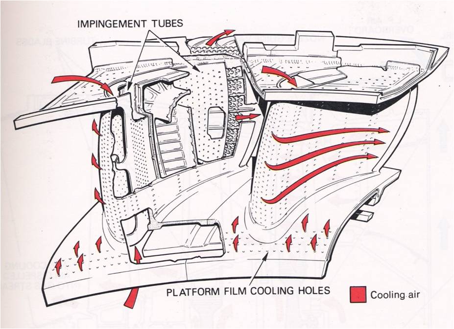
compressor bleed air onto the surface of the blade through the film holes drilled in the surface (Figure 1).
Some of the
major difficulties in developing film cooling strategy is the
sensitivity of the problem to the details of geometrical and
physical conditions, and complex flow dynamics.
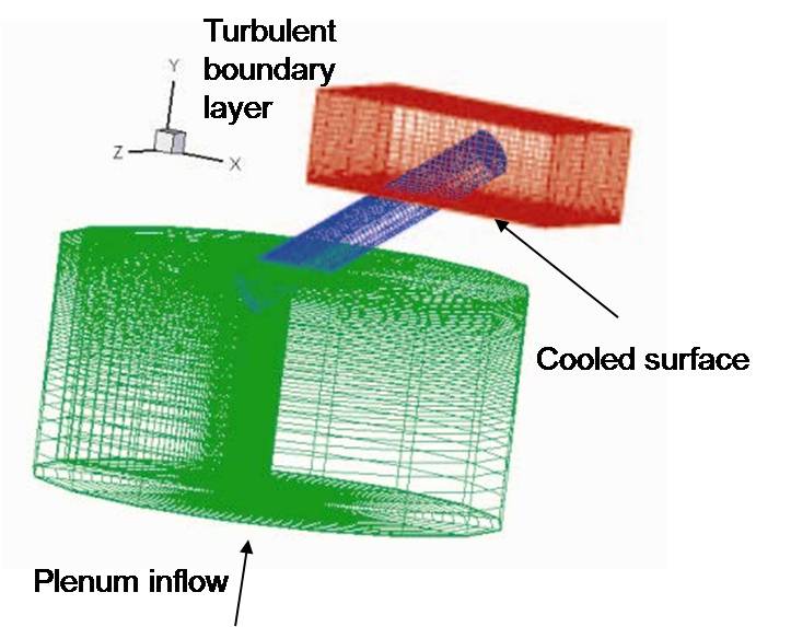
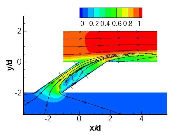
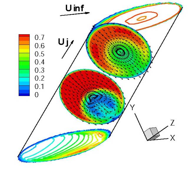
We developed an integrated compressible - low Mach number solver allowing to couple instantaneous dynamics of the flow in the plenum, film hole and above the blade surface in a situation where flow regimes range from supersonic (external flow) to almost stagnating (plenum, M~10^-4) [1]. With the developed solver, we performed LES simulations of film cooling flow issued from an array of inclined cylindrical holes into a flat plate turbulent boundary layer [2, 3]. Collaboration with Dr. David Bogard of UT Austin allowed us to perform detailed comparison between simxulation results and experimental data. Geometrical setup of experiments of Bogard et al. [4] as well as our computational setup are shown in Figure 2.
Figure 1. Rolls-Royce plc, "The Jet Engine"
Renault Printing Birmingham 1996


